
Devo ad un mio caro amico la riscoperta di un vecchio, interessante sistema di ricezione dei segnali. Non sarebbe altro che un eterodina, se non fosse che manca l'alimentazione anodica. Conosciamo già dei sistemi di supereterodina nei quali la valvola mescolatrice non vede l'anodica, ma il segnale dell'oscillatore rivelato. Qui vediamo un ondametro con una valvola R con la sola alimentazione del filamento. Lo strumento, quando riceve un segnale, invece che far accendere una lampadina nel controllo di un trasmettitore o di ascoltare il segnale rivelato da un carborundum, riceve la risultante dell'onda in arrivo e quella dell'oscillazione che, quasi miracolosamente, appare nella valvola disalimentata .
da Bollettino Telegrafico del regio esercito, 1922 articolo del tenente
Angelo Terranova delle officine rt ed e del genio militare
....osservando il circuito si nota che in questo ricevitore si è introdotta una
semplificazione interessante dovuta allo scrivente e cioè che l'eterodina è
priva di batteria anodica. L'unica sorgente è la batteria a 4 volt del
filamento. Questo risultato si è potuto ottenere con l'attacco al punto di mezzo
dell'induttanza alla batteria. L'energia così generata è più debole di quella
della normale eterodina provvista di batteria anodica ma è più che sufficiente
come eterodina in ricezione.
praticamente l'induttanza è tra placca e griglia con presa centrale al + del
filamento, alla griglia arriva anche il quadro di ricezione.
L'articolo dopo le illustrazioni è del 1924
 Continuous wave
syntoniser
Continuous wave
syntoniser
CONTINUOUS WAVE SYNTONISER. BY H. L. CROWTHER,
MSC., Royal Aircraft Establishment, Farnborough.
[MS.re cezved, 30th October, 1924.1
ABSTRACT. The syntoniser is a valve generator of feeble high-frequency
alternating current,
the periodicity of which can be varied over nide limits. The instrument is used
for the measurement
of the wave-length of high-frequencq oscillations and also as a heterod!ne for
C.W. reception.
The instrument described was developed by the l i r Service during the war.
The various applications of this sy-ntoniser and also the method of its accurate
calibration from
a tuning-fork of knon-n frequency are described in detail.
I. GESER~DLE SCRIPTION
THEsy ntoniser is essentially an instrument designed for the accurate
measurement of the
wave-length of continuous high-frequency oscillations, although it can also be
used for other
purposes.
The instrument which is here described was developed by the Air Service during
the
war and was used considerably for both ground and air work.
It is essentially a small generator of high-frequency alternating current, ahich
may, by
the adjustment of a variable condenser, be made to produce oscillations of any
desired
frequency within its range.
It consists of a three-electrode valve x-ith its grid and anode circuits coupled
inductively,
the anode circuit being tuned by a variable condenser. S o extra battery is
required for the
supply of anode current, the effectke E.X.F. n hich maintains the high frequency
current
being the difference of potential between the positive terminal of a 6-volt
filament heating
battery to which the anode is connected and the average potential of the
filament*. In
order to increase this difference of potential between the anode and the average
potential
of the filament, one of the filament terminals of the valve is connected TO the
positire
terminal of the 6-1-0lt battery through a resistance of two ohms. The mean
potentia! of the
grid of the valve is set at tno volts positive by means of a tapping on a h e d
potentiometer
connected across the 6-volt battery, the potentiometer being an internal
component of the
syntoniser.
The grid and anode inductance can both be varied by means of a three-nay switch
in
order to provide sei-era! ranges of viave-lengths as required.
11. GESERALC OSSTRUCTIOS
The following is a description of the general construction of a syntoniser
designed to
cover a range of ivave-lengths from 1000 to goo0 metres. The scale of
wave-lengths is
covered in three ranges:
Range (A) ... ... 1000 to ijoo metres,
Range (B) ... . . , z joo to jooo metres,
Range (C) ... . . . jooo to 9000 metres,
the change from one range to another being obtained by operating a rocker
srritch mounted
on the top panel. Adequate oT-erlap of the ranges is pro\-ided.
* N. Lea, Brit. Pat. 128383 (i9iS).
I 26 H. L. CROWTHER
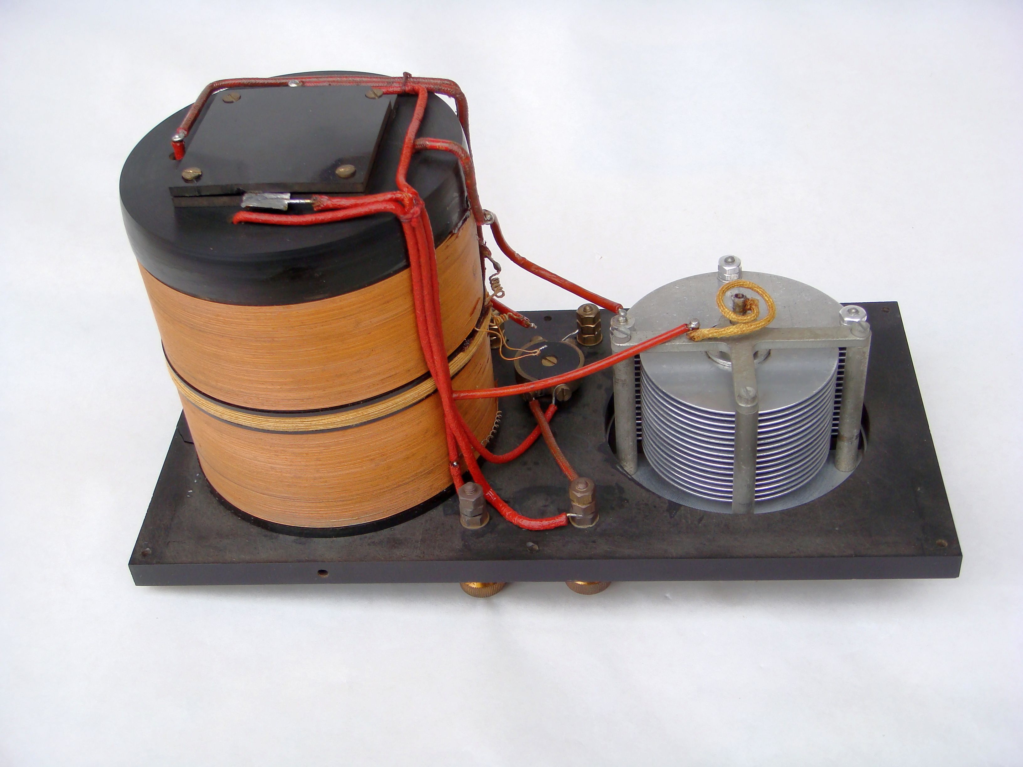
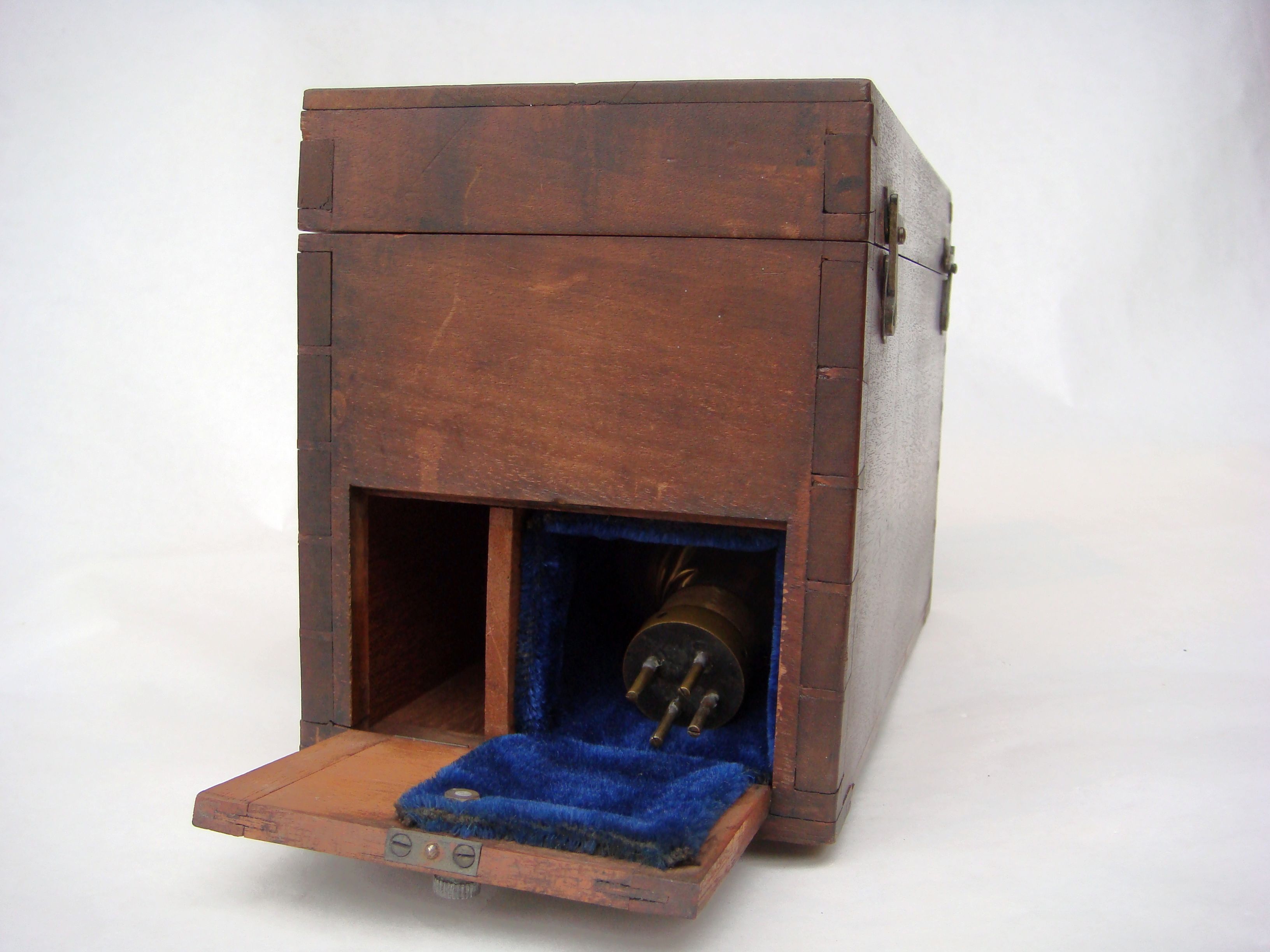
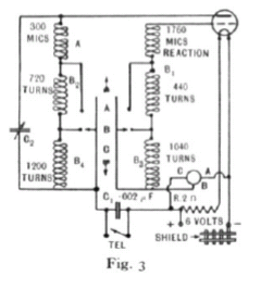
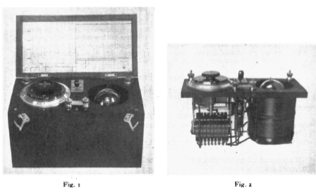
Fig. I gives a general view of the instrument and Fig. 2 its internal
arrangement. Fig. 3
is a diagram of the connections of the circuit.
(a) Anode and Grid Coils
Ran<qe (A): 1000 to 2500 metres. The grid and anode inductances are wound on an
ebonite
tube the inside of which forms the valve chamber. The anode coil is wound in two
sections
Fig. I Fia. 2
joined in series, the grid coil being wound in a groove cut in the valve chamber
between the
two sections of the anode coil.
Range (B): 2500 to 5000 metres. The inductances for this range are made up of
the
inductances used in Range (A) and extra inductances wound on a grooved former.
This former has eight grooves and the windings in
alternate grooves are connected in series. One set of coils
thus forms, with the inductance of Range (A), the anode
inductance, and the other the grid inductance.
Ranp (C): 5000 to 9000 metres. The inductances for this
range are made up of the inductances used in Range (A)
and Range (R), and extra inductances, all being joined in
series. 'l'he extra inductances are wound on another
grooved former, the windings in the alternate grooves being
connected in series. One set of coils forms, with the inductances
of Range (A) and Range (R), the anode inductance,
and the other the grid inductance.
From the diagram of connections shown in Fig. 3, it
will be seen that the rocker switch short-circuits the inductances
which are not being used.
CONTIKVOUS WAVE SYNTONISER 127
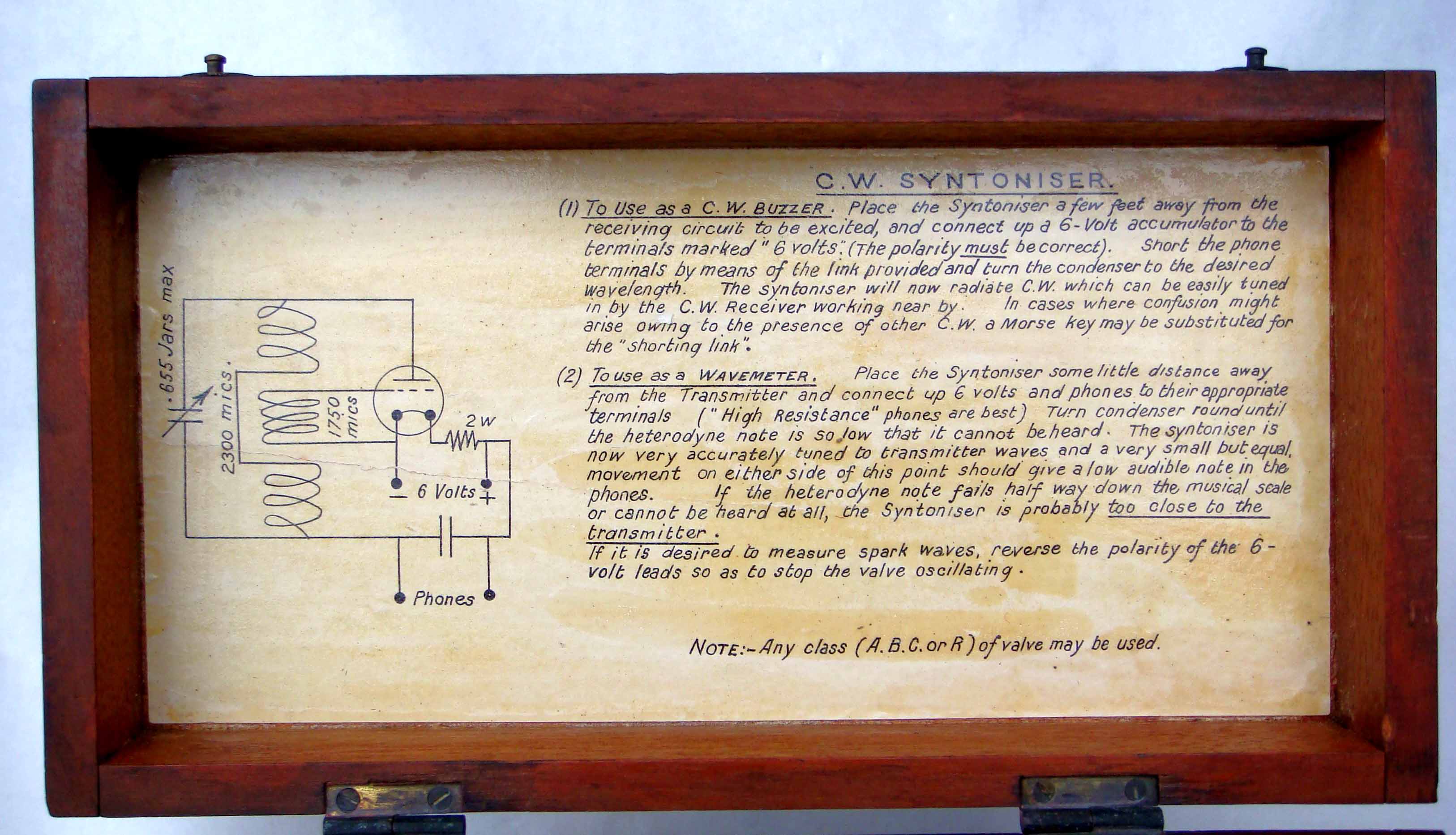
(b) Variable Condenser
This condenser has a maximum capacity of 0~0007j2 p F and forms, with the anode
coils,
the oscillating circuit of the instrument. The rotary dial is of polished
ebonite and is engraved
with three scales. Scale (A) is engraved every 20 metres from 1000 to 2500
metres. Scales
(B) and (C) are engraved every IOO metres from 2jOo to 5000 metres and from 5000
to
goo0 metres respectively, sufficient overlap being provided on each range by
adjustment of
the various inductances.
(c) Wace-length Switck
This switch is of the rocker type and is similar to the standard telephone
listening and
ringing key. There are four movable and eight fixed blades. These are so
interconnected
that the inductances not in use are short-circuited.
The switch changes both anode and grid inductances. It is mounted on the top
panel of
the syntoniser and its three positions are engraved (il), (B), and (C).
(d) Telephones
TKO terminals are provided for connecting telephones when the syntoniser is used
as a
wavemeter for spark or continuous x;ave reception.
The telephones are inserted in the anode circuit of the valve and a link is
provided so that
the condenser which is connected across the telephone terminals may be
short-circuited
when it is desired to use the instrument as an oscillator.
(e) Screen
A screen of copper foil strips is fitted to the inside of the case and is
connected to the
negative battery terminal. The object of this screen is to prevent alteration to
the calibration
by stray capacity.
111. CALIBR4TIOK OF SYSTONISERS
(a) Beats
In the operation of a syntoniser use is made of the well-known phenomenon of
beats.
If a receiver R is placed in the vicinity of two H.F. oscillating circuits A and
B (for example,
two syntonisers), and their respective frequencies are so adjusted as to be
slightly different,
a beat note of pitch corresponding to the difference between the two frequencies
is heard
in the receiver. If the frequency of the circuit oscillating at the higher
frequency is reduced,
the beat note is lowered until what is known as a “nul beat” occurs, at which
point the two
frequencies should be exceedingly close together. If now the frequency of the
same circuit
is gradually reduced, the pitch of the beat note rises again until it becomes
inaudible. The
number of cycles over x-hich a “nu! beat” occurs map be of the order of a
hundred or more
depending on the sensitiveness of the receiver to respond to low-frequency
alternating
currents. That is, nothing may be heard in the telephones for a change of
frequency of one
of the circuits from, say, jo,ooo to 50,100 if the second circuit is tuned to a
frequency of
jo,ojo. This may not be sufficiently accilrate for many purposes, in which case
use is made
of the double beat method of reception. Kith this method a change of frequency
of less than
one cycle per second can be detected. In this method the receiver or a third
circuit is made
to oscillate at a frequency adjusted to give a beat note of approximately j O O
Tvith, say,
circuit A. If circuits A and B had been previously adjusted to approximately the
same
frequent!. by the single beat method, then the pitch of the beat note produced
by A and R,
and B and R might differ to the extent of. say, j o frequency, that is, the two
notes heard
in the telephones may be joc and 450. These different notes give rise to a
second beat in
the telephones vihich by adjustment of circuit B can be made to have a frequency
of, say,
I28 H. L. CROWTHER
one in five seconds. Under these conditions the two circuits A and R are tuned
to a freqriencv
not differing by more than one-fifth of a cycle per second. Alteration in the
frequency of
the receiver or third oscillating circuit makes no difference to the frequency
of this second
beat, as the frequency of the third oscillating circuit is not between the
frequencies of
the first and second circuits. By this method two oscillating circuits can be
tuned to
the same frequency with extreme accuracy.
(h) Ifarmonics
The oscillation of the syntoniscr, or in fact any C.W. valve circuit, is by no
means :I pure
sine wave as most of the odd and even harmonics down to the twentieth or niore
can easily
be detected. ‘I’his means that a syntoniser tuned to a fundamental wavc-lrngth
of, say,
16,800 metres will produce I ‘ nul beats ” in a receiver oscillating at the
follow in^ wavelengths
:
(a) Fundamental wave-length ... ... 16,800 metres
(h) 2nd Harmonic ... ... ... 8,400 .. (4 3rd ... ... ... 5,000 I ,
(4 4th 3 ) ... ... ... 4,200 I ,
( p ) 5th ... ... ... 3,360 .. etc.
, I
1,
Since the receiver is also fairly rich in harmonics it is possible by fairly
tight couplings
to obtain ‘ I nul beats” between harmonics of both receiver and syntoniser.
This production of harmonics by an oscillating valve circuit is extrrmelv
tiseful for c;lIibration
work, but is liable to cause considerable trouble in high power valve
transmission.
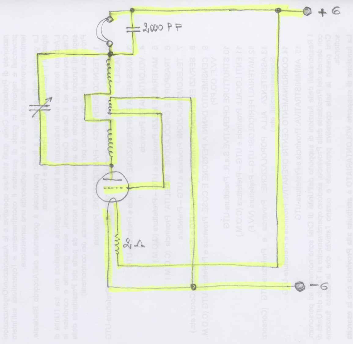
(c) Method of Calibration
In the calibration of a syntoniser reference must be made to some riltim;\te
atantI;lr‘i,
the frequency of which is accrirately known. This standard may he an acct1r;ltely
caIihr;~tctI
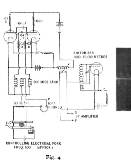
Fig. 4
CONTISUOUS WAVE SYKTOXISER
tuning-fork or a high frequency alternator (say, 8000 -) the frequency of which
can be
determined by mechanical means. The tuning-fork method is now usually employed
for
this work and a rough outline of the method will be described below.
Various valve circuits are known which can be made to oscillate at
audio-frequency, but
there is one which is particularly rich in all the odd and even harmonics. This
circuit,
which is nade use of for wave-length calibration, was developed by Abraham and
Bloch
and is known as the 1Iultivibrator. The connections of this circuit are shown in
Fig. 4,
and an oscillogram of the oscillation after magnification is shown in Fig. j. If
the standard
tuning-fork has a frequency of 1000,th e multivibrator is so adjusted as to give
a note in the
telephones of exactly the same frequency, the two notes being adjusted to
equality by the
usual beat method.
An oscillating circuit can novi be set to definite frequencies by beating with
the various
harmonics of the multivibrator. The following table gives the frequencies at
which ‘‘ double
beats ” occur, assuming that the multivibrator has a fundamental frequency of
1000.
Frequency of
oscillating circuit
at which double Frequency of harmonics of Frequency of
I ‘ nul beats ” occur multivibrator Beat note double beat
10,000 cycles
10600 ,,
11,000 ),
I 1 , j O O ~,
II,joI“ ,,
( 9,000 cycles- 9th harmonic
111,000 ,, -11th ,,
~10,000 ,, -10th ,,
Irz,ooo ,, -12th ~, IO00 ,,
;m; cycles] 0
(11,000 ,, -11th ,,
/io,ooo ,, -10th ,,
/II,OOO ,, -11th ,,
.{IZ,OOO ,, -12th ,,
~ I I , O O O ,, -11th ,,
(IZ,OOO ,, -12th ,,
0
0
0
500 >,
499 >, 2
* This shom the result of hcorrect adjustment.
It can be seen that these double beats occur at frequencies differing by every
500 cycles
per second.
The harmonics to which each beat note corresponds must now be determined. These
can
be found without tracing back to the fundamental of the multivibrator by the
following
method.
Two points on the oscillating circuit giving two wave-lengths, one of which is
twice the
other, the longest being so chosen as to give a double “nu! beat” with the
multivibrator.
are first determined as follow: Let the short and long wave-lengths be
represented b>-
A and ZA respectively. The frequency of 2A is thus accurately a multiple of joo
cycles per
second. The wave-length A can now be fixed by another oscillating circuit tuned
to the
second harmonic of zA, i.e. a wave-length of A.
The number of “nul beats” S occurring betmeen the points of the oscillating
circuit A
and zA inclusive is now determined. As shown in the above table, these “nul
beats”
correspond to frequencies differing by joo. Then
Frequency of 2.A = (S- I) joo.
In order to f i p~oi nts on a syntoniser with fixed differences of wave-length
between them
instead of points which differ by a constant frequency, it is necessary
accurately to tune an
oscillating circuit to a ware-length corresponding to the differences required.
That is, if
a syntoniser is required to be calibrated at wave-lengths of every IOO metres,
the standard
oscillating circuit must be tuned up to the latter. This can be done by the
method described
above by using a suitable number of steps. It cannot be done in one step as the
harrnonics
J.S.I. 9
130 H. L. CROWTHER
of the multivibrator become exceedingly close together for wave-lengths below
20,ooo
metres.
Points on the syntoniser which produce “ nul beats ’’ with the Ioo-metre
oscillating circuit
car, now be determined and these are accurately IOO metres apart. In spite of
the multiplicity
of the “ nul beats ” under these conditions it is impossible to make a mistake
so long
as one makes sure that there are a definite number of them between two
wave-lengths
which have been determined independently, e.g. between wave-lengths of 1000 and
2000
metres there must be eleven “nul beats” inclusive of those occurring at 1000 and
2000
metres.
(d) Variation in the Calibration of a Syntonisei,
Kith the same valve and a constant 6-volt filament battery the calibration of a
syntoniser
probably remains accurate to within one-tenth of I per cent. for a very
considerable
period, assuming that no distortion of the variable condenser or variation in
the value of
the inductances takes place. When telephones are used in conjunccion with the
instrument
a small correction may be required.
The use of an extra anode battery may alter this calibration very considerably.
For accurate measilrements, therefore, neither telephones nor high tension
battery should
Khen a valve is changed the calibration of the instrument should be checked.
be used.
11-. THE VSE OF THE SYNTOKISER
(a) To Tune up a C. W. Transmitter
Khen extreme accuracy is not required, the sptoniser itself may be used as the
receiver
by connecting a pair of telephones in the anode circuit of the valve. The
instrument is
placed in the vicinity of the transmitter and the transmitter tuned until a “nul
beat” is
heard at the required wave-1engTh. Care must be taken not to have the syntoniser
too close
to the transmitter as the former is liable to cease oscillating if the coupling
is too tight.
If the wave-length of the transmitter has been adjusted to the correct value, I
‘ nul beats ”
will be obtained for wave-length settings of the syntoniser 2, 3, 4, j, etc.,
times the fundamental
n-ave-!ength and for wave-lengths 8, 4, $, i, etc., of the fundamental
wave-length.
If great accuracy is required, then the double beat method with a separate
receiver must
be employed (see I11 (a)).
(bj To Tune in a C.W. Receiver
The syntoniser is set to the desired n-ave-length and placed near the receiver,
and the
latter is nom tuned until the “nul beat” is found. If the tuning is correct,
“nul beats”
will be heard for every multiple of the fundamental wave-length, e.g. if the
receiver has
been tuned up to 1000 metres, “nul beats” will be obtained for syntoniser
settings of
1000, 2000, 3030, poo, etc., metres.
(c) The Syntoniser used as a Separate Heterodyne
With high frequency amplifiers it has been found advisable to use a separate
heterodyne
for C.W. reception. For this purpose the spntoniser is placed in the vicinity of
the receiver
and tuned approximately to the wave-length of the incoming signal to give a
suitable note
in the telephones. This note should not be affected by the tuning of the
receiver. In this
case no extra anode potential need be applied to the syntoniser. Without
high-frequency
amplification an anode battery is generally found necessary.